
Based on recent site audits in abrasive granite circuits, the biggest threat to profitability isn’t the upfront equipment price of the primary crusher, but the hidden wear and capacity bottlenecks caused by poor material flow synchronization. When designing a multi-stage aggregate plant, the primary crushing stage dictates the rhythm for every subsequent machine. If the jaw crusher is improperly configured, the entire circuit suffers from inconsistent feed and excessive downtime.
The Engineering Reality of Primary Reduction Ratios
The reduction ratio of the primary jaw crusher establishes the baseline for the entire aggregate plant’s capacity.
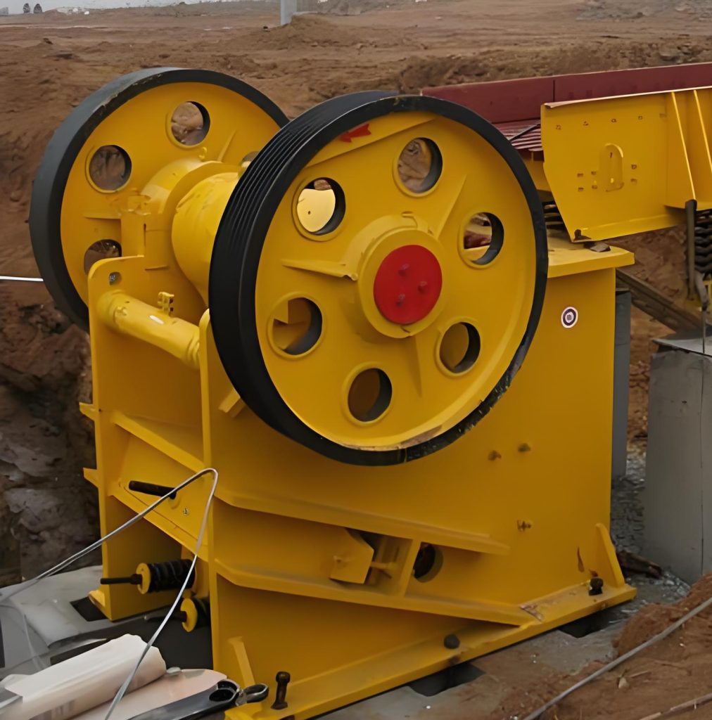
A critical mistake in plant design is assuming the primary jaw can handle any rock that fits in the opening. The physical reality of the crushing cavity dictates otherwise. Pushing a PE Series Jaw Crusher to its maximum theoretical reduction ratio increases the load on the eccentric shaft and forces the toggle plate to operate near its breaking point. In hard rock applications, this aggressive setting leads to rapid wear on the fixed and movable jaw plates. A more conservative reduction ratio at the primary stage, passing a slightly larger feed to the secondary crusher, often yields a higher overall production-to-cost ratio by extending wear part life and stabilizing power draw.
Material Flow Synchronization: Preventing Downstream Starvation
An unbalanced circuit where the primary jaw outpaces the secondary cone crusher leads to immediate material bridging and unplanned stops.
Synchronizing the material flow requires precise alignment of the jaw crusher’s discharge with the secondary stage’s acceptance capacity. Consider a circuit utilizing a high-capacity secondary cone crusher. If the PE jaw is set to a wide Closed-Side Setting (CSS) to maximize throughput, it may produce a top size that exceeds the cone’s maximum feed opening. Conversely, choking the jaw to produce a finer feed will restrict the primary throughput, leaving the high-capacity cone starved and running inefficiently. The solution is calculating the mass balance and setting the jaw’s CSS to deliver a consistent feed gradation that perfectly matches the secondary stage’s requirements.
Feed Size Limitations and Cavity Choking
Feeding oversized boulders into the jaw crusher creates severe cavity blockages, spiking motor amperage and halting production.
The maximum feed size is not merely a suggestion; it’s a structural boundary. For instance, the PE900x1200 is rated for a maximum feed of 750mm. Introducing material exceeding this dimension risks severe bridging above the crushing zone. The material forms an interlocking arch, requiring manual intervention to clear—a dangerous and time-consuming process. The resulting amperage spikes can trip the thermal overload protection on the 130kW motor. Consistent pre-screening and blasting control are mandatory to prevent these bridging events and ensure a continuous multi-stage granite crushing circuit.
Synchronized Equipment Matrix
To handle the abrasive silica of river gravel at 150 tons per hour, we have engineered the following circuit:
| Process Stage | Recommended Model | Capacity (tons per hour) | Max Feed (mm) | Power (kilowatts) |
|---|---|---|---|---|
| Primary Crushing | PE600~900 | 60-130 | 500 | 75 |
| Secondary Crushing | HPT200 | 90-250 | 185 | 160 |
| Vibrating Feeder | GZD-1100~4200 | 120-240 | 600 | 15 |
Field Wear Benchmarks: Synchronizing PE600~900 with Abrasive Granite
- Capacity (tons per hour): 60-130
- Power (kilowatts): 75
- Weight (T): 16
- Max Feed (mm): 500
Technical Index: LH-PE JAW CRUSHER APPLICATION IN AGGREGATE PRODUCTION-August/2026-Ref-#82914
Solution Architect’s Log: Aligning PE Series Capacity for Multi-Stage Operations
How do we manage the surge loads from the primary jaw to prevent overloading the secondary cone? In our recent field tests, we observed that an intermediate surge pile or a properly sized buffer hopper is mandatory between the jaw and cone stages. This decoupled arrangement prevents the erratic discharge of the jaw from causing amperage spikes in the secondary crusher’s motor. What happens if the primary jaw is consistently fed with material near its maximum size limit? Historically, running a jaw crusher continuously at its maximum feed limit accelerates fatigue on the eccentric shaft and toggle plate. The machine is forced into a constant state of peak stress, leading to premature bearing failure and significantly reduced capital payback velocity. Can we adjust the jaw’s CSS to compensate for a smaller secondary crusher? Do not tighten the jaw’s CSS beyond the manufacturer’s recommendations just to protect downstream equipment. This drastically reduces the jaw’s capacity and transfers the bottleneck to the primary stage, starving the entire circuit. How does moisture content affect the jaw’s effective throughput? Data shows that materials with high moisture and clay content will stick to the jaw plates, reducing the effective volume of the crushing cavity. This “packing” reduces throughput by up to 20% and requires a wider CSS to prevent choking.
Optimizing Material Flow in High-Volume Granite Circuits
Ignoring the fundamental relationship between the primary jaw’s reduction ratio and the secondary crusher’s feed requirements guarantees a choked circuit and a disastrous production-to-cost ratio. When you push a PE600~900 past its 500mm maximum feed limit, or fail to synchronize its discharge with the 185mm feed limit of an HPT200, the resulting material bridging and amperage spikes will inevitably lead to cracked toggle plates and ruined eccentric shafts next month. Analyze your circuit mass balance immediately.
Stop Guessing on Circuit Synchronization
“Let’s map your material flow and identify the exact bottleneck in your primary reduction stage.” — From the Desk of your Solution Architect
- > Construction Waste Mobile Impact Crusher for Recycled Aggregate Production
- > Jaw Crusher for Crushing Volcanic Rock in Indonesia
- > Portable Gold Ore Cone Crusher in South Africa
- > Crawler Mobile Cone Crusher for Fine Crushing in Gold Mining
- > Application of PF Series Impact Crushers in Highway and Railway Construction
- > The Role of the Jaw Crusher in African Copper Mining Projects
- > Application of Fixed Cone Crushers in Metal Ore Crushing
- > How to Process Clay-Rich River Gravel with a Jaw Crusher: Effective Solutions


Online


Message