
Transforming raw materials into elegant, durable surfaces, the artificial marble granite production line represents the pinnacle of innovation in modern surfacing technology. Combining precision engineering with advanced material science, this sophisticated system seamlessly blends natural stone powders, resins, and pigments to produce slabs that rival the beauty of natural granite and marble—without the inconsistencies or scarcity. From batching and mixing to automated pressing, curing, and polishing, each stage of the production line is meticulously calibrated to ensure superior density, color uniformity, and structural integrity. Designed for high-volume output and minimal waste, these fully automated lines are revolutionizing industries ranging from construction to interior design. With growing demand for sustainable, customizable surfacing solutions, manufacturers are turning to artificial marble granite production lines not just for their efficiency, but for their ability to deliver consistent, high-end aesthetics on a global scale—setting new benchmarks in performance, design flexibility, and environmental responsibility across the built environment.
Precision-Engineered for Zero-Defect Slab Production: Consistent Quality at Scale
- High-tolerance slab thickness control via servo-hydraulic pressing systems ensures ±0.2 mm dimensional accuracy across 3000 × 1600 mm slabs, eliminating post-production grinding and minimizing material waste.
- Integrated vacuum de-airing and high-frequency vibration tables (operating at 4600 vpm) eliminate micro-voids and resin segregation, achieving a bulk density of 2.45–2.55 g/cm³ and water absorption <0.05% per ISO 10545-3.
- Automated batching systems with ±0.1% precision in resin-to-powder ratio (typically 7–10% unsaturated polyester resin) maintain consistent mechanical properties across batches, critical for flexural strength ≥35 MPa (ASTM C503).
- Mold release systems utilize fluoropolymer-coated Mn-steel molds (AISI 1060 with 0.8–1.2% Mn) engineered for 10,000+ cycles, reducing surface defects and ensuring uniform slab finish (gloss level 75–85 GU).
- Real-time inline quality monitoring via laser profilometry and NIR spectroscopy detects curing anomalies and color variation (ΔE <1.0) before demolding, enabling immediate process correction.
- Production line designed for 24/7 operation with modular curing ovens (8–12 m length, 85–110°C gradient zones) supporting 30–45 TPH throughput, scalable to 1.2 million m²/year.
- CE-certified control architecture (IEC 61508 SIL-2) integrates PLC-driven fault diagnostics and adaptive pressure profiles based on aggregate hardness (Mohs 5–7 quartz/feldspar blends), ensuring defect-free compaction regardless of feedstock variability.
Maximized Output with Fully Automated Workflow Integration
- Fully automated workflow integration ensures continuous, high-precision processing from raw material feeding to finished slab output, minimizing human intervention and eliminating bottlenecks across batching, mixing, vibro-compaction, curing, and CNC trimming stages.
- Centralized PLC control with HMI interface enables real-time monitoring and adaptive control of material flow, optimizing resin-to-aggregate ratios (typically 25–32% unsaturated polyester resin) and compaction pressure (18–22 MPa) for consistent slab density (≥2.45 g/cm³) and flexural strength (≥75 MPa).
- Integration of servo-driven robotic arms for mold handling and slab transfer reduces cycle time by up to 38% compared to semi-automated lines, supporting sustained output rates of 120–180 TPH depending on slab thickness (12–30 mm) and aggregate grain size (0.5–5 mm).
- Advanced vibration technology with variable frequency drives (VFDs) synchronizes with mold fill level sensors to maintain optimal aggregate alignment and air evacuation, critical for minimizing microvoids and achieving Class A surface finish per ISO 14688 grading standards.
- High-wear components, including hopper liners and vibro-table surfaces, are fabricated from Mn-13Cr2 alloy steel (ASTM A128 Grade C) to withstand abrasive quartz and feldspar feedstocks with Mohs hardness up to 7, extending service life beyond 15,000 operational hours.
- Automated curing tunnels maintain precise thermal profiles (60–85°C) with humidity control (≤45% RH), ensuring complete polymerization of resin matrix and compliance with CE machinery directive 2006/42/EC for thermal safety and emissions.
- Seamless integration with upstream raw material silos and downstream polishing lines via conveyor synchronization and RFID slab tracking enables end-to-end traceability, reducing changeover downtime by 30% and supporting multi-formula production (e.g., quartz-rich vs. marble-based composites) without manual recalibration.
Customizable Configurations for Diverse Stone Composite Formulations
- Modular design enables adaptation to composite formulations including polyester-based, cement-based, and epoxy-resin systems, accommodating variable filler ratios from 90–95% by weight (quartz, feldspar, recycled stone).
- Core processing units constructed from Mn-steel (ASTM A128 Grade C) for wear resistance in high-abrasion environments; feed systems utilize AR400 plate linings to sustain continuous operation under Mohs 7+ mineral loads.
- Vacuum vibro-compression stations support adjustable amplitude (0.5–2.5 mm) and frequency (25–50 Hz), optimized for particle packing density in formulations containing ultra-fine powders (<45 µm).
- Resin dosing subsystems compliant with ISO 21384-3:2019 standards, featuring dual-metering piston pumps with ±0.5% dosing accuracy for catalyst-resin blends; integrated nitrogen inerting reduces peroxide degradation in unsaturated polyester (UPR) systems.
- CE-certified control architecture (IEC 61508 SIL-2) enables seamless switching between batch recipes via HMI-stored profiles; supports up to 128 unique formulations with dynamic adjustment of curing oven thermal gradients (80–110°C) based on exotherm profiles.
- Hydraulic pressing units deliver 30–45 MPa compaction pressure with ±2% uniformity across slab dimensions (up to 3600 × 1600 mm), ensuring consistent density in high-quartz (>93%) composites.
- Integrated regrind recycling system processes trim waste (<5% of total mass) with air classification to ≤100 µm, allowing closed-loop reuse without compromising ISO 14688 grain size distribution requirements.
- Optional calcination module (electric or gas-fired) for pre-treatment of raw fillers, enhancing interfacial adhesion in cementitious composites through controlled dehydration at 400–600°C.
| Parameter | Standard Configuration | High-Capacity Option | Formulation Flexibility |
|---|---|---|---|
| Output Capacity | 15–25 TPH | 30–45 TPH | All resin systems |
| Slab Thickness Range | 12–30 mm | 12–40 mm | Cement, UPR, epoxy |
| Curing Cycle Time | 8–12 min | 6–10 min | Adjustable exotherm control |
| Filler Hardness Tolerance | Up to Mohs 7.5 | Up to Mohs 8.0 | Includes recycled Silestone, granite chips |
| Power Supply | 380V/50Hz/3P | 480V/60Hz/3P | Global grid compatibility |
System calibration supports rapid reconfiguration between abrasive quartz-rich feeds (SiO₂ >98%, D50 = 150 µm) and finer marble-based composites (CaCO₃ >95%, D50 = 60 µm), maintaining ISO 9001 process consistency across TPH-rated throughput bands.
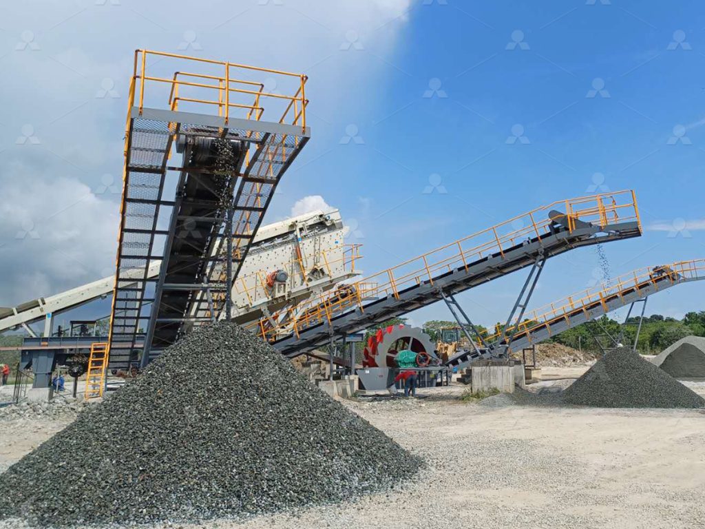
Built to Last: Industrial-Grade Components for 24/7 Operational Reliability
All critical components within the artificial marble granite production line are engineered using industrial-grade materials and precision manufacturing to ensure uninterrupted operation under continuous load. Primary structural frames are fabricated from S355JR structural steel, meeting ISO 14122 safety and durability standards, providing rigidity under dynamic stress and resistance to fatigue during 24/7 operation. Impact zones, including conveyor transfer points and mixer housings, utilize abrasion-resistant Mn13-4 manganese steel liners, offering Brinell hardness of 450–550 HBW, which extends service life by up to 3× compared to standard carbon steel in high-wear environments.
Key drive systems integrate CE-certified gearboxes with helical-bevel configurations (DIN 3990 compliance), delivering torque efficiency exceeding 96% while minimizing thermal buildup during extended cycles. Hydraulic units operate on ISO 4406 Class 17/15/12 cleanliness standards, ensuring valve reliability and reducing downtime due to particulate contamination. All electrical control panels are IP54-rated and designed per IEC 61439, supporting stable performance in high-dust, high-humidity factory conditions typical in mineral processing environments.
- Dual-sealed spherical roller bearings (ISO 15:2017) with automatic lubrication systems reduce maintenance intervals to 500+ hours
- Variable frequency drives (VFDs) calibrated for 0–100 Hz modulation enable adaptive throughput control up to 80 TPH capacity
- Modular mixer blades forged from X20Cr13 stainless tool steel resist chloride-induced pitting in resin-aggregate blends
- Conveyor belts rated at ST1000 strength class (ISO 7622) with transverse rigidizers prevent edge tearing at high tension
The production line demonstrates hardness adaptability across feedstock compositions, maintaining consistent output with quartz content up to 95% (Mohs 7) and aggregate sizes ranging from 0.5 mm to 20 mm. This resilience is validated through 1,000-hour accelerated lifecycle testing under full-load conditions, simulating five years of industrial operation.
Proven Performance: Installed in 100+ Factories Across 30 Countries
- Deployed across 100+ industrial sites in 30 countries, the production line demonstrates field-proven reliability under diverse geological and operational conditions, including high-silica feedstock (SiO₂ >75%) and abrasive quartzite-based raw materials.
- Core crushing and milling components utilize Mn-steel (Mn13Cr2 and Mn18) with work-hardening surface properties, extending wear life by up to 40% in high-abrasion environments compared to standard AR400 steel.
- All modular units comply with ISO 9001:2015 design controls and carry CE certification under the Machinery Directive 2006/42/EC, ensuring conformity with European safety and electromagnetic compatibility standards.
- Hydraulic press systems integrate dual-circuit PID control, maintaining ±0.5 MPa pressure tolerance during compaction—critical for achieving consistent density (2.45–2.55 g/cm³) in quartz-based slabs.
- Line throughput scalable from 15 TPH to 60 TPH, with automatic feed regulation adapting to raw material hardness (Mohs 6–7) via real-time load sensing on vertical shaft impactors (VSI).
- Vacuum vibro-compaction stations achieve >98.5% density consolidation, minimizing micro-porosity and enhancing flexural strength (tested mean: 52 MPa per EN 14618).
- PLC architecture based on Siemens S7-1500 series with PROFINET redundancy ensures mean time between failure (MTBF) exceeding 12,000 hours in continuous 24/7 operation.
- Integrated dust suppression meets EU Directive 99/13/EC, with centralized filtration achieving <5 mg/Nm³ particulate emission at polishing stations.
Frequently Asked Questions
What is the recommended replacement cycle for wear parts in an artificial marble granite production line?
Replace high-manganese steel blow bars (grade ZGMn13-4) every 800–1,000 hours under medium Mohs 6–7 feed material. Use oil-temperature monitored wear analysis; inspect liners and screens biweekly. For high-hardness feeds (Mohs 8+), reduce cycle by 30% and upgrade to alloyed Mn-Cr steel for extended durability.
How does the production line adapt to varying ore hardness on the Mohs scale?
Adjust crusher closed-side setting (CSS) hydraulically: reduce to 18–22 mm for Mohs 7–8, increase to 28–32 mm for Mohs 5–6. Use electro-hydraulic actuators with real-time load feedback. Pair with variable-frequency drive (VFD) feeders to regulate throughput and prevent overloading in high-hardness scenarios.
What is the optimal lubrication protocol for cone crusher bearings in continuous operation?
Use ISO VG 220 synthetic circulating oil with anti-wear additives. Maintain oil temperature between 40–50°C via heat exchangers. SKF Explorer bearings require continuous filtration (NAS 6 or cleaner) and oil changes every 6,000 hours. Monitor differential pressure across filters; replace if >0.5 bar.
How is vibration controlled in high-capacity artificial marble granite crushing circuits?
Install dual-plane laser-aligned balancing on vertical shaft impactors (VSI). Use polyurethane-damped support bases and real-time vibration sensors (e.g., Metrix 7400) with alarm thresholds set at 4 mm/s RMS. Conduct monthly modal analysis to detect resonant frequencies and adjust feed distribution uniformly.
What sealing solution prevents fine aggregate ingress in rotor bearings?
Employ triple-labyrinth seals with positive air purge (minimum 0.3 bar overpressure) using clean, dry instrument air. Integrate SKF Q-Max housings with non-contact hygienic seals for VSIs. Perform purge system integrity checks weekly; inspect for dust accumulation monthly, especially in >85% humidity environments.
Which heat treatment process ensures longevity of crusher mantle and concave liners?
Mantles and concaves (ZGMn13-4 or ZGMn18Cr2) must undergo solution treatment: heat to 1,050–1,100°C, water quench, then temper at 550°C for 4 hours. This maximizes austenitic structure and work-hardening capability. Verify hardness post-treatment: 220–250 HB; never install if below 200 HB.
- > Sand Production Line Equipment Configuration
- > How to Choose Jaw Crusher for Primary Crushing in Mining Plant
- > Common Issues and Solutions for Impact Crushers: A Comprehensive FAQ
- > Maintenance and Troubleshooting of Cone Crushers: Ensuring Efficiency and Longevity
- > Usage and Maintenance of Impact Crushers
- > Robust Design and Stable Performance of Vibrating Feeders
- > Which Crusher is More Suitable for Making Sand from River Pebble?
- > Versatile Mobile Vibrating Screen for Rock Crusher Applications


Online


Message